Chainage
Using the Chainage Section
The Chainage Section let's you reference Alignment, on their own or as part of a Network.
Create an Alignment
To create an Alignment, select a line, polyline or set of lines and polylines, and click Add From Selection.
Pango sorts and stitches the lines together by start and end points into one continuous Alignment, ignoring noisy items such as tick marks or cross lines. Items that cannot be stitched to the longest Alignment are ignored. If needed, you may reuse them to make a separate Alignment later.
The point with the smallest X,Y coordinates is chosen as the km 0.0 start of the Alignment, and labelled tick marks are displayed overlaid on the geometry. If you cannot see the labels, click the Analyse Mesh button in the Panel toolbar and move the cursor over the 3D view to trigger a re-render.
Adjust the Alignment Start km
To flip the start and end points, click the  Invert Alignment button.
To change the start km of the Alignment, type the start km value in the Start At control. Alternatively, if you have a reference point such as a labelled tick mark in your geometry or a known chainage point, activate the  Snap mode, click the item with the known chainage, and type the chainage value in the popup dialogue. The start km is automatically offset by the required value to match the known point.
Overlay Controls
In the overlay sub section, you can choose the content, format and condition of display of the overlay for the Alignment.
- Choose one of the Display Mode from:
- Always: the overlay is always displayed
- Closest: the overlay is displayed this Alignment is the closest to the Mesh being analysed, hidden otherwise or if there is no Mesh selected
- Never: the overlay is never displayed, although the chainages are still being calculated
- Activate the Alignment overlay for the Alignment geometry to be traced back on top of the view, whether the original geometry is displayed or not
- Activate the Tick & Labels overlay to display the chainages points and associated chainage value, with options for:
- Spacing: the minimum distance between labels when zoomed in to the closest. Note that chainages labels overlay are adaptive, and as you zoom out, the smaller subdivisions are omitted showing only the larger or most appropriate divisions, which could be 10, 100 meters or kilometres apart.
- Offset: the distance between the label and the tick mark on the Alignment. Labels are displayed on the right by default but you can toggle display on the other side using Display on the Left
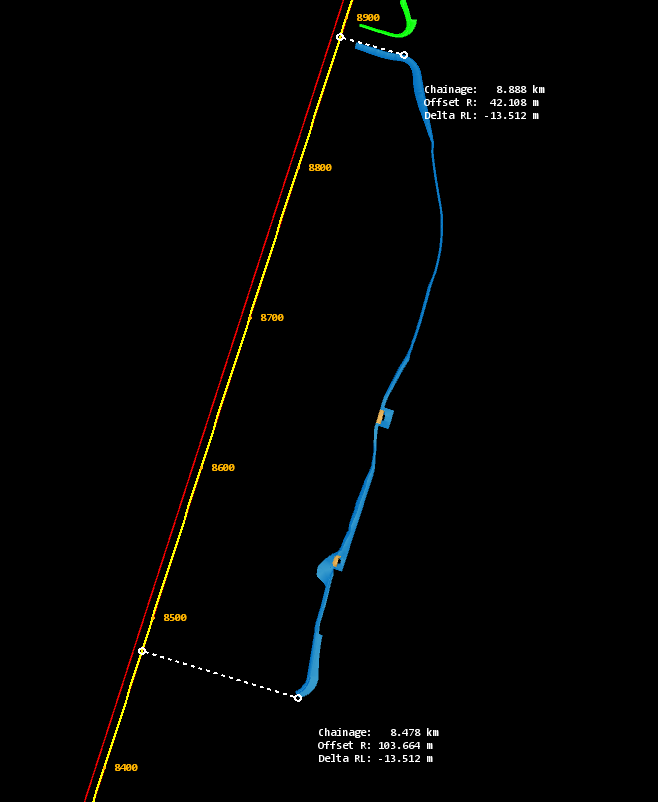
- Activate the From/To option to overlay the selected mesh points that have respectively the lowest and highest chainage, along with their projection information
- Activate the Closest/Furthest option to overlay the selected mesh points that are respectively the closest and furthest away from the Alignment, along with their projection information
Multiple Alignments in Networks
You can have more than one Alignment at any given time. To add more Alignment, such as up and down track or secondary roads, repeat the steps from the Create an Alignment section above.
Each Alignment can be given a name, and different display options. For instance the Main Alignment can be set on Display Mode 'Always', while the secondary roads Alignment can be set on Display Mode 'Closest', thus only showing when the Mesh being analysed is closest to it.
